Link to github repo with all the files
Introduction
I’ve always been fascinated with 3D graphics and volumetric displays - I spent a good chunk of my high school years building tools to draw and animate 3D models, in Visual Basic for DOS no less (this was the early ’90s!). I even skipped my high school prom to go and compete in a software development competition with one of my tools (which I won, though I don’t think my girlfriend of the time appreciated that :) )
Obligatory shaky-cam footage - will update if anyone is at all interested in this
I’m writing this retrospectively, almost a year after I completed this project. I’m not a writer by inclination and I’m not sure who will want to read this but I feel that I need to contribute back to the “community” - if this helps someone in their project, I’ll sure it will be worth the effort.
I ran across the Globe project a couple of years ago and it got me thinking about how I might build something similar. My day job involves a lot of cloud based app development (well, a lot of meetings about cloud based app dev, not so much hands-on coding anymore) and I’m always looking for interesting projects that will help me maintain my embedded development skills, where my passion lies. This project seemed challenging enough that I wasn’t quite sure about the intricacies of how to build this - but it was obviously possible as someone had done it. I had an advantage over the Globe project - I just had to build a one-off and not worry about building for reliability and durability (and cost and shipping and… well you get the idea). Does this project have any end-use? As a wise person once said, it’s not the destination, it’s the journey :)

What follows is a break-down of the various parts of the project. It took about 8 months to design, learn and build, sometimes only working an hour or two a week, as time and life allowed. I don’t have enough pictures of the build process but hopefully there’s enough here to be of use to someone.
High Level Breakdown
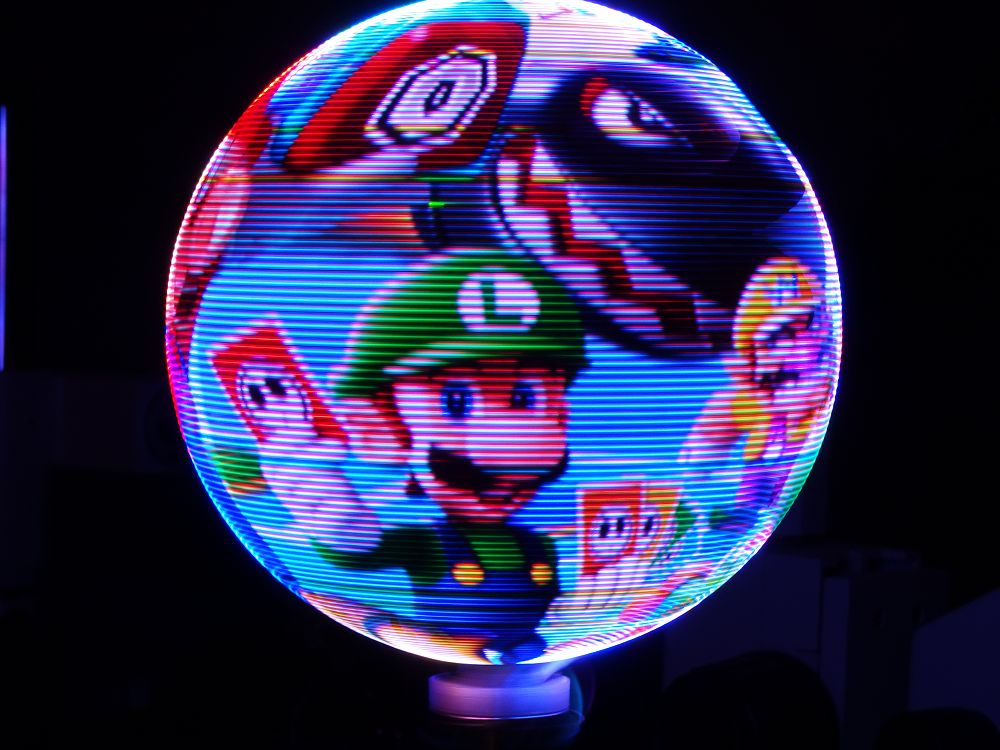
The goal of Flicker is to display images on a spherical surface - a great application of this is to display an animation of the map of Earth. It’s essentially a circular PCB with LEDs mounted on its periphery that is spun at about 15 revolutions per second - by turning on specific LEDs at the right time during each revolution, you can essentially draw in mid-air using the Persistence of Vision effect. Probably the biggest challenge of this project is determining where the PCB is during each instance in its revolution - any jitter in angular position tracking translates directly into jitter in the image, which your eye is quick to pick up on. The other challenge is getting data from an image source and getting a bunch of LEDs to turn on fast enough that you can get some sort of decent resolution. This translates to a few requirements:
- decent resolution: I was shooting for 256 pixels by 512 “slices” of the sphere. Didn’t quite meet the first goal (at least not the intention) but exceeded the second goal
- multiple shades of color (greatly exceed this goal)
- 15 RPS (check)
- should be able to show animations (yup)
- reasonable cost (all other bills kept getting paid, kids were fed, etc… :-) )
As an aside, let’s talk about resolution. The PCB has a number of LEDs around its edge and that defines one aspect of resolution that can’t be changed - in this case, it’s 256 pixels. Then, as the PCB spins, you can take an angular slice of the space that the LEDs sweep through the air - the angular resolution. The angular resolution is a function of how well you can determine the PCB’s angular position and your ability to turn the LEDs on and off quickly. To put some numbers on this. If you assume:
- each LED needs 24 bits of color information
- there are 256 LEDs
- you’re spinning the PCB at 15 RPS
- you have 1024 angular slices per revolution
you end up having to push about 94Mbits per second around on the board. That’s not a huge number and definitely doable.
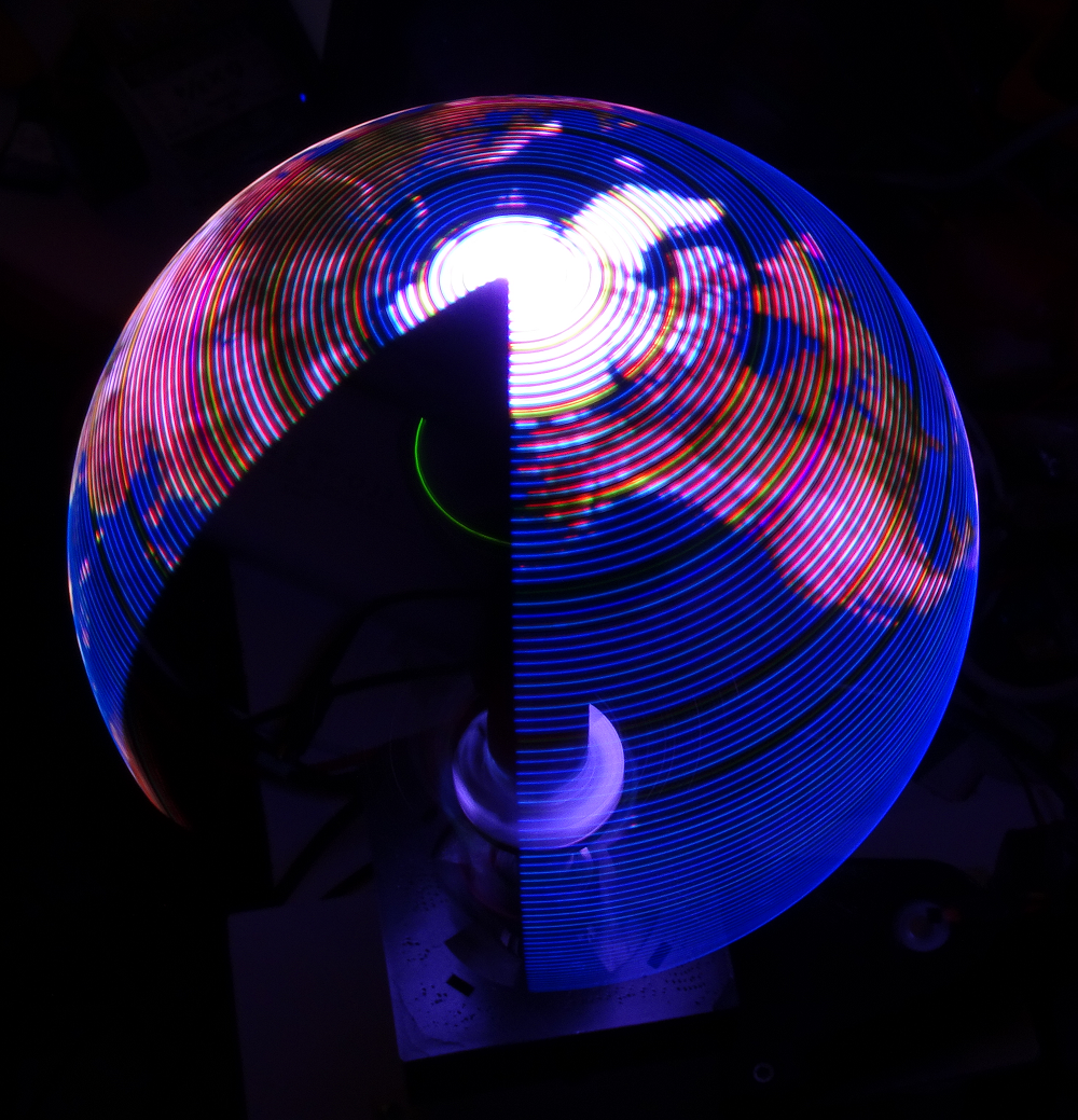
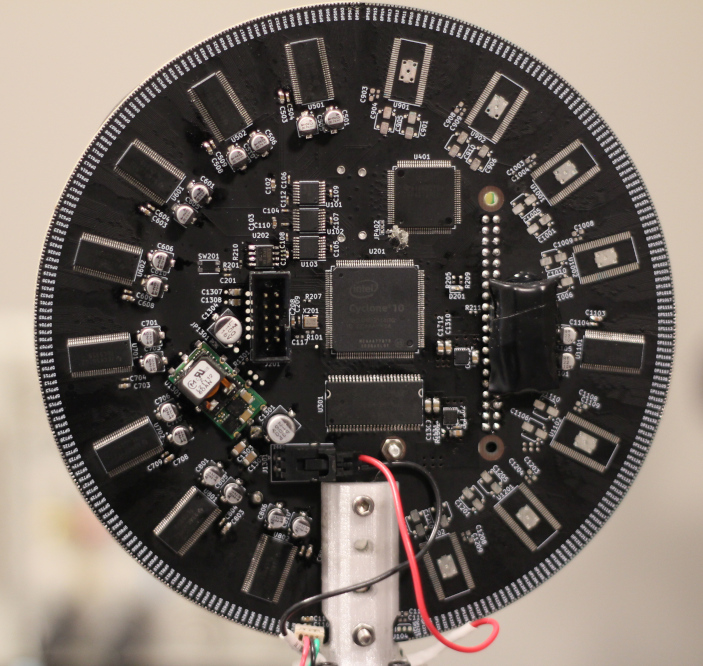
In the image above, you can see the green LED from a Raspberry Pi inside the globe.
Let’s get into the individual sub-systems.
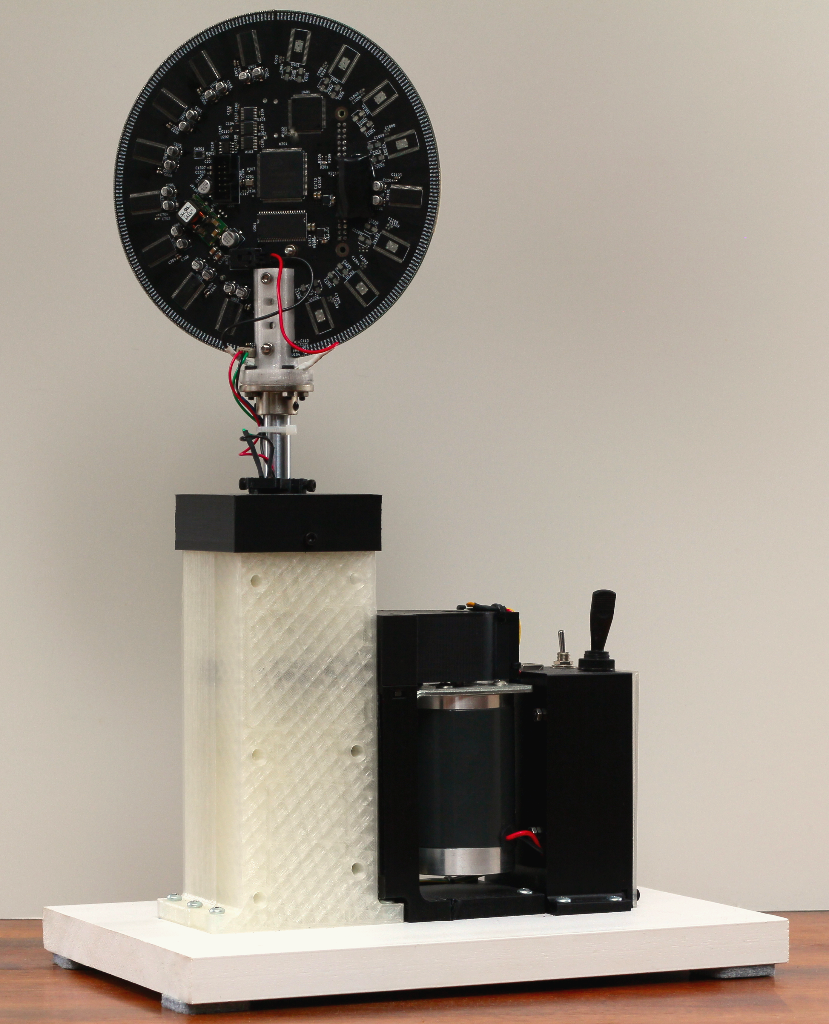
Mechanical Breakdown
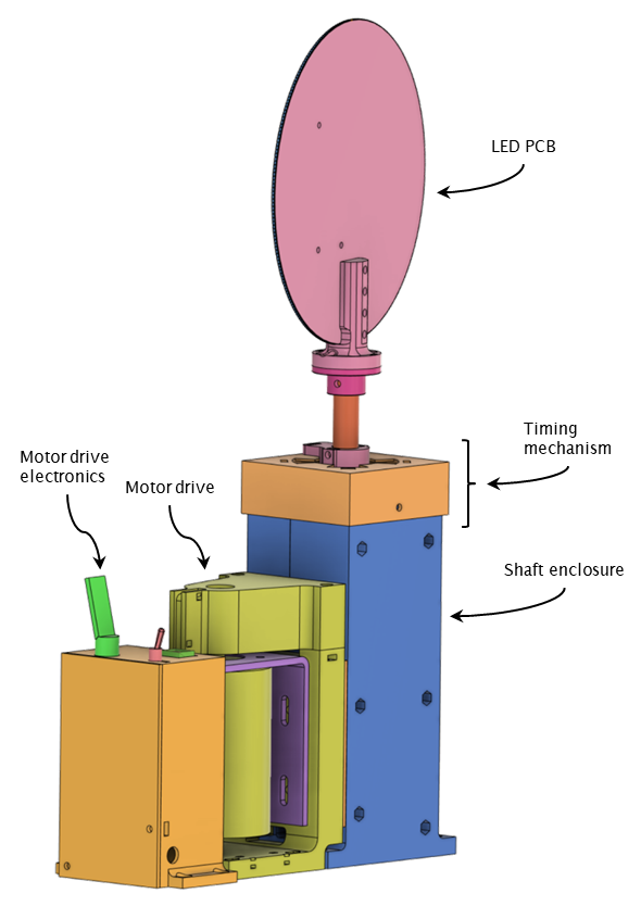
The mechanical system for Flicker is pretty simple. There’s a brushed motor driving a shaft, which has the PCB mounted on it. The motor is driven by a small Arduino and motor driver board - the Arduino measures the motor speed using a magnet and hall-effect switch. The motor drives the shaft using a 3:1 belt and pulley reduction system. There’s nothing really critical about the motor system - not a lot of thought was put there and it’s definitely oversized (but again, this isn’t for production.)
You might notice that the LED PCB is kind of swinging out there all alone - how does it get power or talk to anything? Well, the board is almost completely self-contained (we’ll get to that soon) - it only needs power. The board gets its power through wires fed through a hollow 16mm OD shaft, via a slip-ring. It took a while to find a slip-ring that would work at these speeds (900 RPM) - I think this one is rated at 600RPM. I’m not too worried about it as I’m only pushing power through it (12V), not any communications lines. It has 12 lines total so I’m using half of those lines for each of power and ground. I probably won’t get the full rated life-time out this slip-ring but again, not for production :)
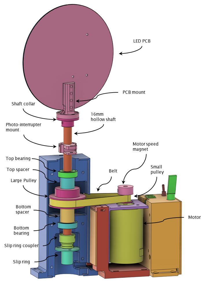
A little metal shaft collar mounts to the shaft using a couple of grub screws. A 3D printed PCB mount is bolted to the shaft collar. The bottom half of the shaft collar is also hollow to allow the power wires to exit out of the shaft.
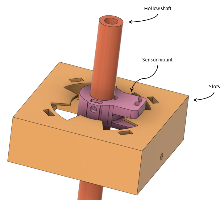
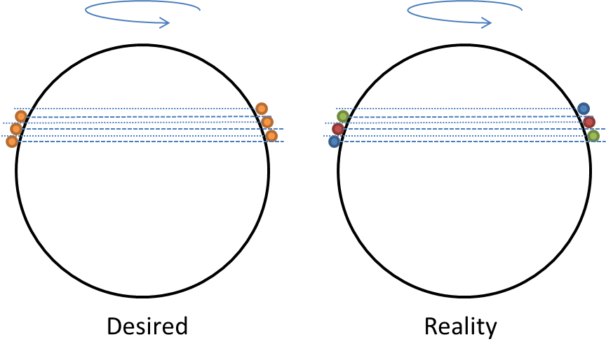
I had initially decided to use a hall effect sensor mounted to the PCB and a magnet fixed to the structure to determine the speed of rotation of the shaft for the electronics, as well as a “home” or front position. This worked poorly - it turns out the motor shaft speed wasn’t constant during its entire revolution, something I never expected. This caused jitter in the image.
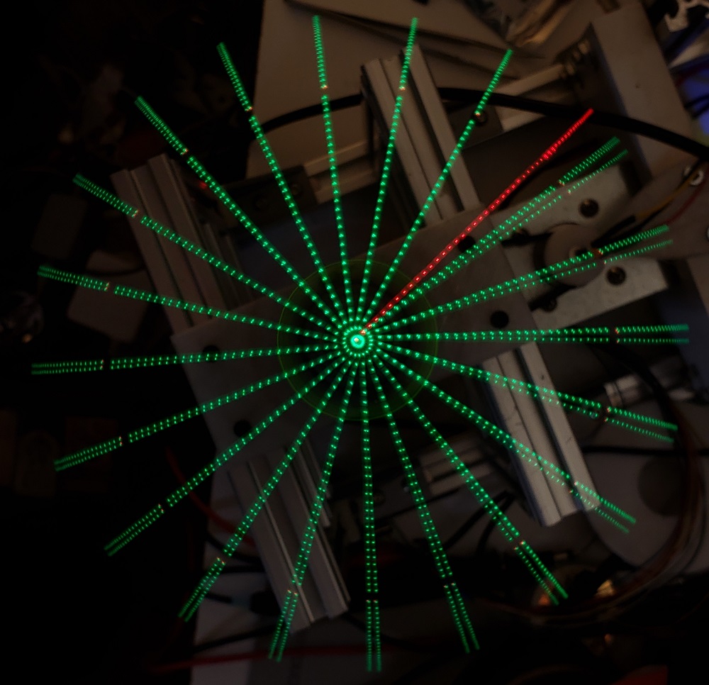
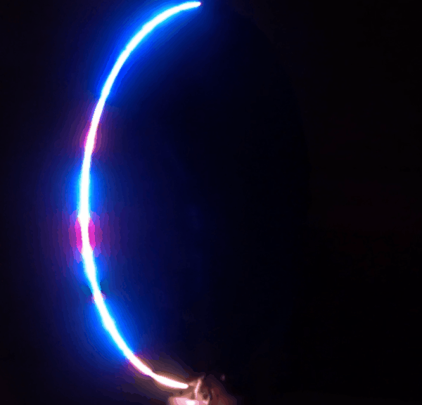
In the timelapse picture above, Flicker is displaying what should be equidistant green lines, with a red line indicating the home position. The board is spinning counter-clockwise. You can see that the lines are initially positioned properly but as time elapses, there is more and more jitter in the angular position of the green lines.
I tried detecting multiple magnets so I could get a better estimate of speed at multiple points in the shaft’s revolution but it also seemed that the hall sensor had some timing jitter. I ended up scrapping this arrangement and using a slot based photo-interrupter system that turned out to be accurate enough for this project. By measuring the time it takes for the photo sensor to change state (I measure both edges), I get a good enough instantaneous speed estimation. The sensor mount component is a bit bigger than I wanted but since I have no way of machining metal (and thus adding a threaded hole), I can’t use grub screws (maybe a helicoil would work? but I don’t have any on hand). It works, but I would love to have a small lathe and milling machine for this kind of part (don’t get me wrong, I love my 3D printer!)
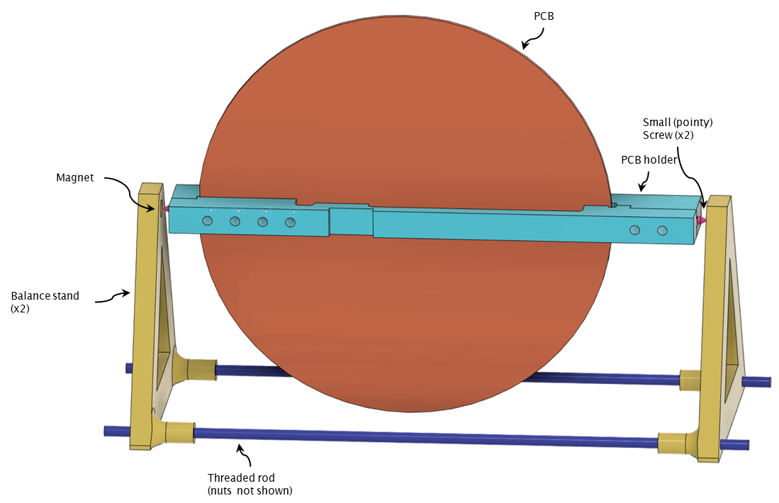
You may have driven a car with a wheel that was slightly out of balance - even a few grams of imbalance can cause large vibrations in a mutli-ton vehicle. Here we have a PCB spinning at 15 revolutions per second - fast enough that small imbalances will cause the entire machine to shake itself apart. Knowing that, I took a cue from the balancing jigs drone builders use to balance their props and built something similar. Once the board is fully populated, I can clamp it in a custom designed PCB holder. The holder has a couple of sharp screws pointing out each end - those screws are attracted to magnets in the balance stand and make good bearings. Once in the jig, I can spin the board around, adding weights to ensure that it’s balanced well enough. It’s not perfect but it does the job (did I mention that this is a one-off?) The weights are currently just hot-glued to the PCB but I do have a nice little 3D printed weight-holder to install at some point.
Electrical Breakdown
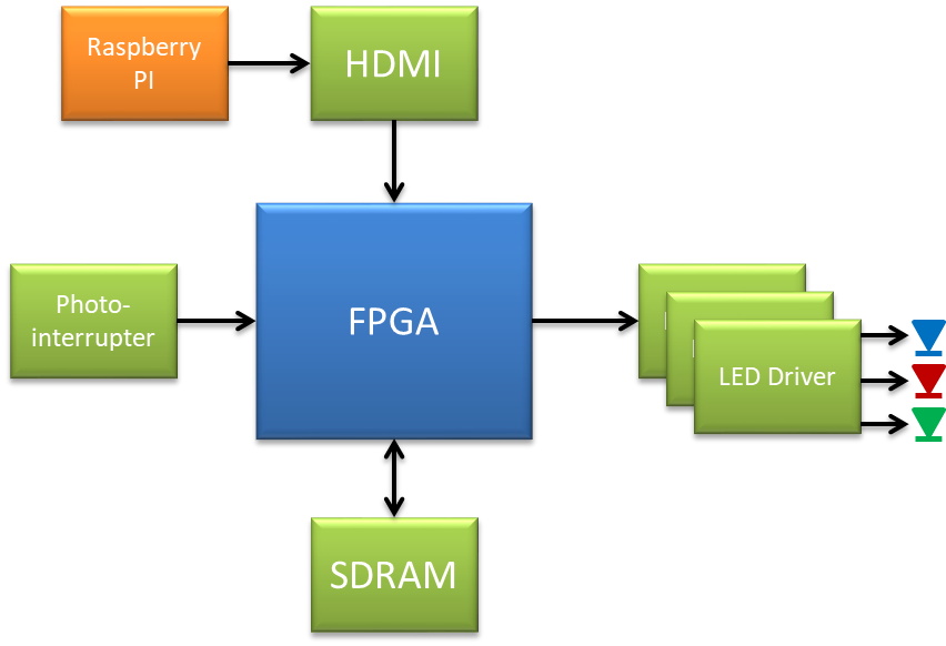
The electronics have three main tasks to do:
- Decode an image from the HDMI port and save it in memory
- Figure out the angular position of the PCB
- Send the right slice of image data to the LED drivers at the right time
There’s a lot going on concurrently. Could I do this in a microcontroller? Maybe one with good DMA capabilities and a relatively high clock speed but I have my doubts (and I’m not looking to be thaaaat challenged :) ) I think this is a great use for an FPGA and that’s what I chose to use.
Here’s a link to the schematics in PDF form
FPGA
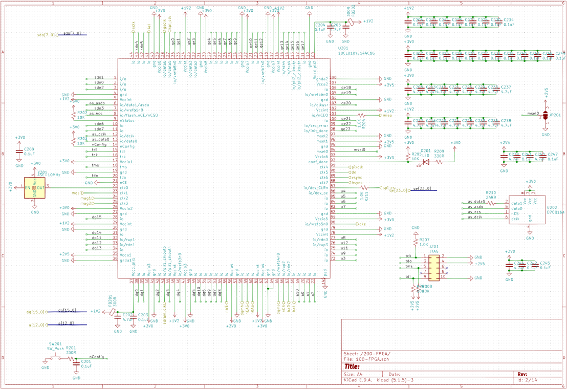
After refreshing myself on the world of FPGAs, I chose an Altera (or Intel I guess now) Cyclone 10 LP to drive this project. It’s relatively cheap and hobbyist friendly (comes in a TQFP package), has enough IO pins, good docs, free (enough) dev tooling, etc. I’ll go over the FPGA code shortly but I did spend some time prototyping the code in Quartus to make sure I’d have enough resources in the FPGA for what I wanted to do (I did and lots of space to spare). I also did some pin planning, again to make sure I had enough resources on chip. Note that I also incorporated a configuration EEPROM to save the FPGA “program” on-board, as well as JTAG to program both the FPGA and the config device, as well as to provide real-time debugging capabilities (super useful!)
RAM
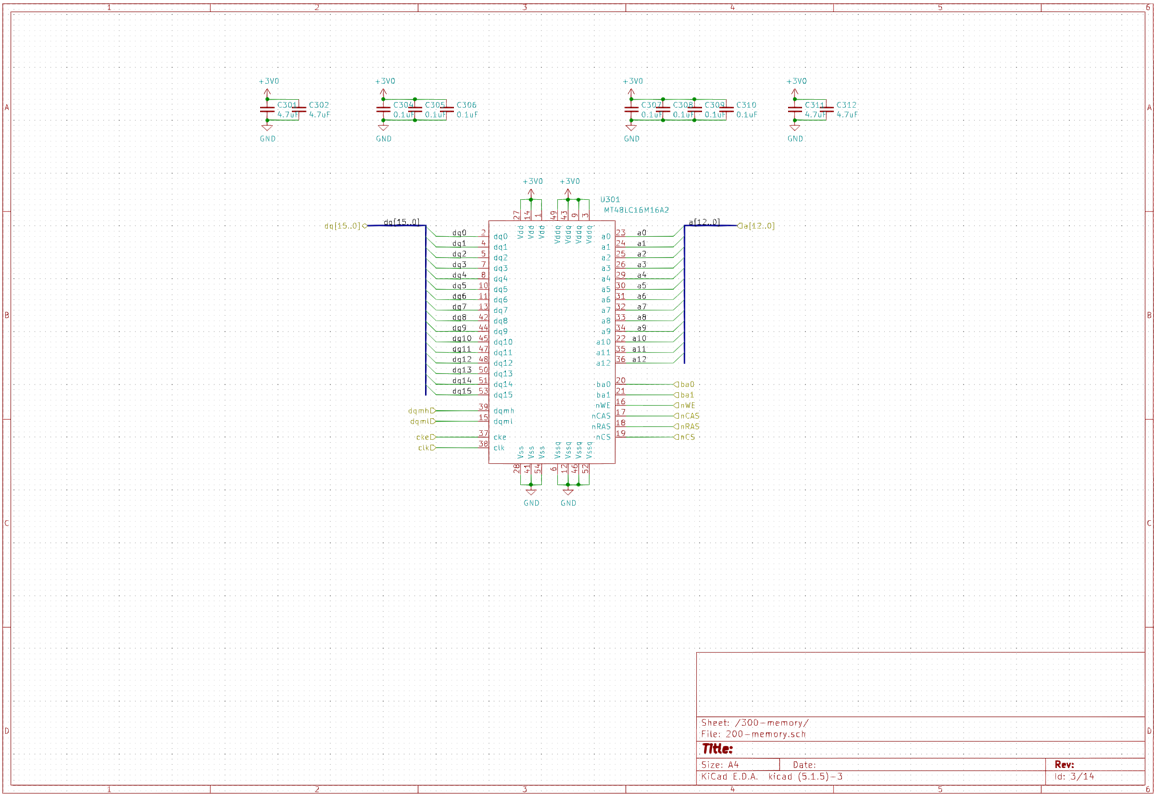
I’m not going to say much about the RAM but suffice to say that it’s a MT48LC16M16A2 SDR SDRAM configured as 4M x 16bit x 4 banks, with all the genius/evilness that goes along with dynamic RAM (seriously, who ever imagined that memory that forgets everything every few milliseconds was a good idea?!?)
Video Input
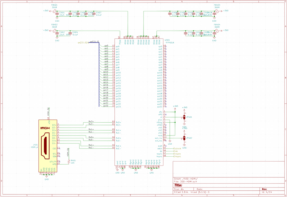
The DVI decoder is pretty standard (HDMI and DVI use the same basic signaling standard). A TFP401 takes care of decoding the HDMI signals and pushing out a 24 bit color datastream, along with associated pixel clock, vsync and hsync signals. I made a choice here that I came to regret when writing the FPGA code. I chose to have the pixel clock run continuously, rather than be gated by the data valid signal DE generated by the DVI decoder. While I routed the DE signal to the FPGA, there were some interesting timing challenges that prevented me from using it properly. I chose the easier route and did a little board surgery to reverse that decision. Luckily, that was the only error on the board!
LEDs
The RGB LEDs are small, surface mount LTST-C19HE1WT that are 1.6mm square and 0.35mm thick. Even though the datasheet calls the lens “White Diffused”, it’s pretty clear - I was hoping for something much more diffused.
The LEDs are driven by TLC5955 chips. Each chip can drive 16 RGB LEDs (so 48 outputs) at a 16 bit brightness resolution. A serial clock clocks in serial data into an internal shift register and a latch signal is used to update the LEDs. A high speed clock clocks the PWM generators. A high PWM frequency is important - if it’s too slow, you won’t be able to get the angular resolution you need. For this chip, we can drive a PWM clock of up to 33MHz, which if we used the full 16 bits of the PWM counters would mean we could update the LEDs at about 503Hz. Assuming a 15RPS rate and 1024 angular slices per revolution, we need at least a 15x1024=15,360Hz update rate. So on the face of it, the TLC5955 wouldn’t work for this application. However, if you read the datasheet carefully, there are a couple of interesting points:
- setting the TMGRST control bit means that a latch rising edge resets the internal PWM counter.
- the TLC5955 has an “Enhanced Spectrum” PWM mode. It’s a bit hard to describe but essentially it divides the PWM cycle of 65536 clock periods into 128 consecutive bins. If the brightness data for a specific LED has a value of 1, a single bit in the first bin is set to 1. If the data is 2, a 1 is placed in 2 of the bins. This continues to 0x0080, which will put a 1 in all 128 bins. A value of 0x0081 will cause all the bins to have a single 1 and one of the bins to have 2 1’s. Essentially brightness values that are multiples of 128 will cause all the bins to be populated by a number of ones equal to the brightness value divided by 128. Check out this link if you want more information on how this ES-PWM mode works.
The TLDR: by using this ES-PWM mode, you can effectively multiply the PWM frequency by 128 if you choose your data values as multiples of 0x0080 and use the TMGRST mode to reset the PWM counter whenever you need to update the brightness data. The downside is that you end up with 9 bits of effective brightness, but that’s more than enough for this application. 503Hz times 128 is much greater than the 15kHz we need so it turns out we can use this chip after all.
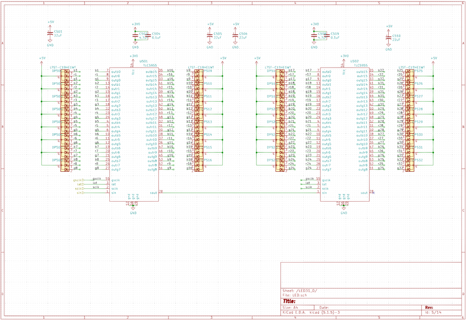
There are 16 TLC5955 chips to drive the 256 RGB LEDs. The chips are daisy-chained in pairs - this allows the FPGA to clock out 8 serial data streams at the same time rather than one long data stream. This keeps the time to update all the LEDs low enough to support the desired angular resolution.
Power
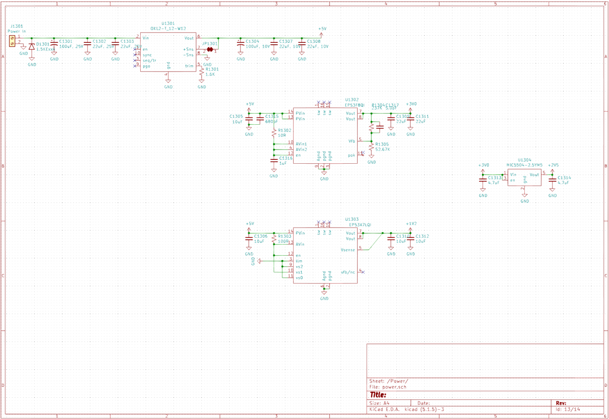
There are three DC/DC converters on the board. One is a module that takes the 12V from the slip ring and generates +5V. Two other buck converters generate +3.3V and +1.2V. The +3.3V is used board wide, while the +1.2V is used solely by the FPGA. A LDO makes +2.5V for the FPGA analog circuitry.
Connecting it all together
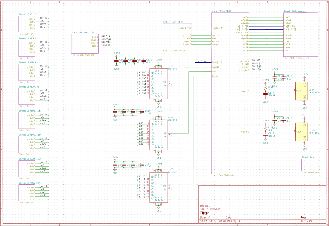
Because I ran out of FPGA pins, I chose to have a single pin for each of the clock, data clock and latch signals for all the LED drivers. To ensure that I had no fanout issues, those signals are fed to Si53365 fanout clock buffers, which buffer the signals to each pair of TLC5955 chips.
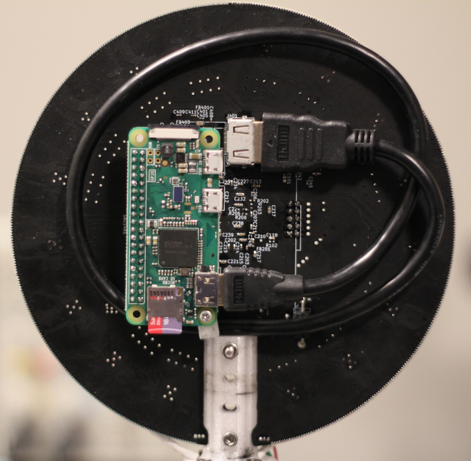
I used a Raspberry Pi Zero W to generate the HDMI signals for the FPGA - it’s small enough to mount on the PCB. This gave me a nice and cheap way to store and display images and videos as well as a way to control the display wirelessly. I had hoped that I would be able to communicate with the Pi while it was spinning but it really doesn’t work. Surprisingly, while SSH doesn’t work while the board is spinning, the Wifi connection isn’t dropped so things still seem to be talking to each other. I also routed the SPI signals to the FPGA in case I ever wanted to configure some internal FPGA parameters on the fly from the Pi (like individual LED brightness) - I never got around to implementing this but haven’t really needed it either.
PCB
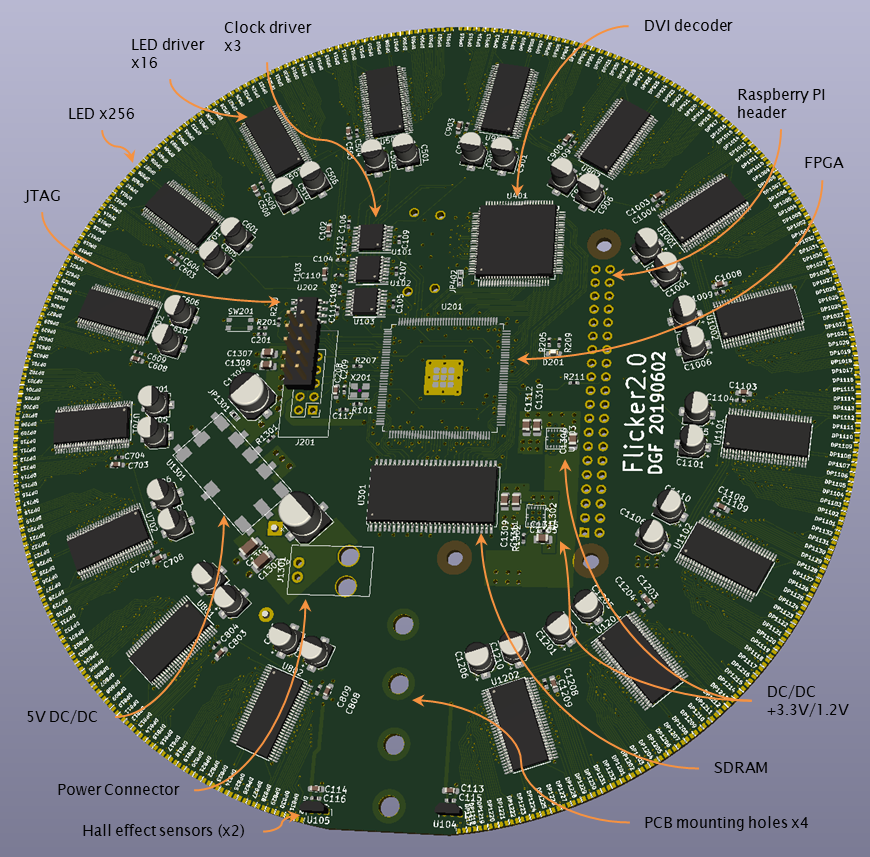
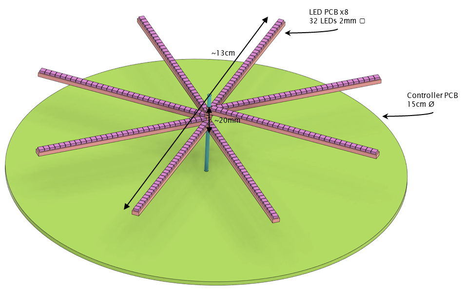
The PCB is a 4-layer board, 6mil trace/space, 8mil holes manufactured by JLCPCB (who I highly recommend). The board is 15cm in diameter.
Note that this is Flicker 2.0 - Flicker 1.0 was another design using addressable LEDs in a different form factor that was never built.
I need a shorter HDMI cable :-)
Here’s a link to the PCB layers in PDF form
To place the LEDs, drivers, supporting capacitors and associated text fields accurately on the PCB, I wrote the following script for Kicad:
#!/usr/bin/env python2
# -*- coding: utf-8 -*-

import math
from pcbnew import *

pcb = GetBoard()

ToUnits = ToMM
FromUnits = FromMM

Radius = 150.0/2.0
NumLEDs = 256
NumDrivers = math.ceil(NumLEDs / 16)
HalfAngle = 170.0
CompHeight = 2.8
DriverRadius = Radius - 15
CapAngle = 3.5
CapRadius = Radius - 27
CenterX = 108.50626
CenterY = 99.62642

Sheets = ["5", "6", "7", "8", "9", "10", "11", "12"]

allComponents = pcb.GetModules()

def place():
    cnt = 0
    #place LEDs
    for sheet in Sheets:
        for chip in range(32):
            LED = "DP" + sheet + '{:02d}'.format(chip+1)
            positionLED(cnt, LED)
            cnt = cnt + 1

    #place LED drivers
    cnt = 0
    for sheet in Sheets:
        positionDriver(cnt, "U" + sheet + "01");
        positionDriver(cnt+1, "U" + sheet + "02");
        cnt += 2

    #place big caps
    cnt = 0
    for sheet in Sheets:
        positionCap(cnt, sheet)
        positionCap(cnt+1, sheet)
        cnt += 2

    Refresh()

def getDriverAngle(idx):
    if(idx < NumDrivers/2):
        angle = 90.0 + HalfAngle / (NumDrivers/2.0) * idx + HalfAngle / (NumDrivers/2.0) / 2
    else:
        angle = 90.0 - HalfAngle / (NumDrivers/2.0) * (idx - NumDrivers/2.0 + 1) + HalfAngle / (NumDrivers/2.0) / 2  - (HalfAngle / (NumLEDs/2.0)/2 )
    return angle

def positionCap(idx, sheetName):
    angle = getDriverAngle(idx)

    if(idx % 2):
        part1 = pcb.FindModuleByReference("C" + sheetName + "06")
        part2 = pcb.FindModuleByReference("C" + sheetName + "10")
    else:
        part1 = pcb.FindModuleByReference("C" + sheetName + "01")
        part2 = pcb.FindModuleByReference("C" + sheetName + "05")

    x1 = math.cos(math.radians(angle-CapAngle)) * CapRadius + CenterX
    y1 = -math.sin(math.radians(angle-CapAngle)) * CapRadius + CenterY
    part1.SetPosition(wxPoint(FromUnits(x1), FromUnits(y1)))
    part1.SetOrientation((angle+180) * 10.0)
    part1.SetLocked(True)

    x2 = math.cos(math.radians(angle+CapAngle)) * CapRadius + CenterX
    y2 = -math.sin(math.radians(angle+CapAngle)) * CapRadius + CenterY
    part2.SetPosition(wxPoint(FromUnits(x2), FromUnits(y2)))
    part2.SetOrientation((angle+180) * 10.0)
    part2.SetLocked(True)

def positionDriver(idx, partName):

    part = pcb.FindModuleByReference(partName)
    angle = getDriverAngle(idx)

    if(idx < NumDrivers/2):
        part.SetOrientation((angle+90.0)*10.0)
    else:
        part.SetOrientation((angle+90.0) *10.0)


    angleRad = math.radians(angle)

    x = math.cos(angleRad) * DriverRadius + CenterX
    y = -math.sin(angleRad) * DriverRadius + CenterY


    part.SetPosition(wxPoint(FromUnits(x), FromUnits(y)))
    part.SetLocked(True)


def positionLED(idx, partName):
    if idx < NumLEDs/2:
        angle =  90.0 + HalfAngle / (NumLEDs/2.0) * idx
    else:
        angle = 90.0 - HalfAngle / (NumLEDs/2.0) * (((math.floor(idx/16)+1)*16 - idx % 16) - NumLEDs/2.0) - (HalfAngle / (NumLEDs/2.0) / 2 )

    angleRad = math.radians(angle)

    x = math.cos(angleRad) * Radius + CenterX
    y = -math.sin(angleRad) * Radius + CenterY

    part = pcb.FindModuleByReference(partName)
    part.SetPosition(wxPoint(FromUnits(x), FromUnits(y)))
    part.SetOrientation((angle-90.0)*10.0)
    part.SetLocked(True)

    ref = part.Reference()
    ref.SetKeepUpright(False)
    ref.SetTextAngle(900)

    xr = math.cos(angleRad) * (Radius - CompHeight) + CenterX
    yr = -math.sin(angleRad) * (Radius - CompHeight) + CenterY
    ref.SetPosition(wxPoint(FromUnits(xr), FromUnits(yr)))

    ref.SetTextHeight(FromUnits(0.6))
    ref.SetTextWidth(FromUnits(0.6))
LEDs
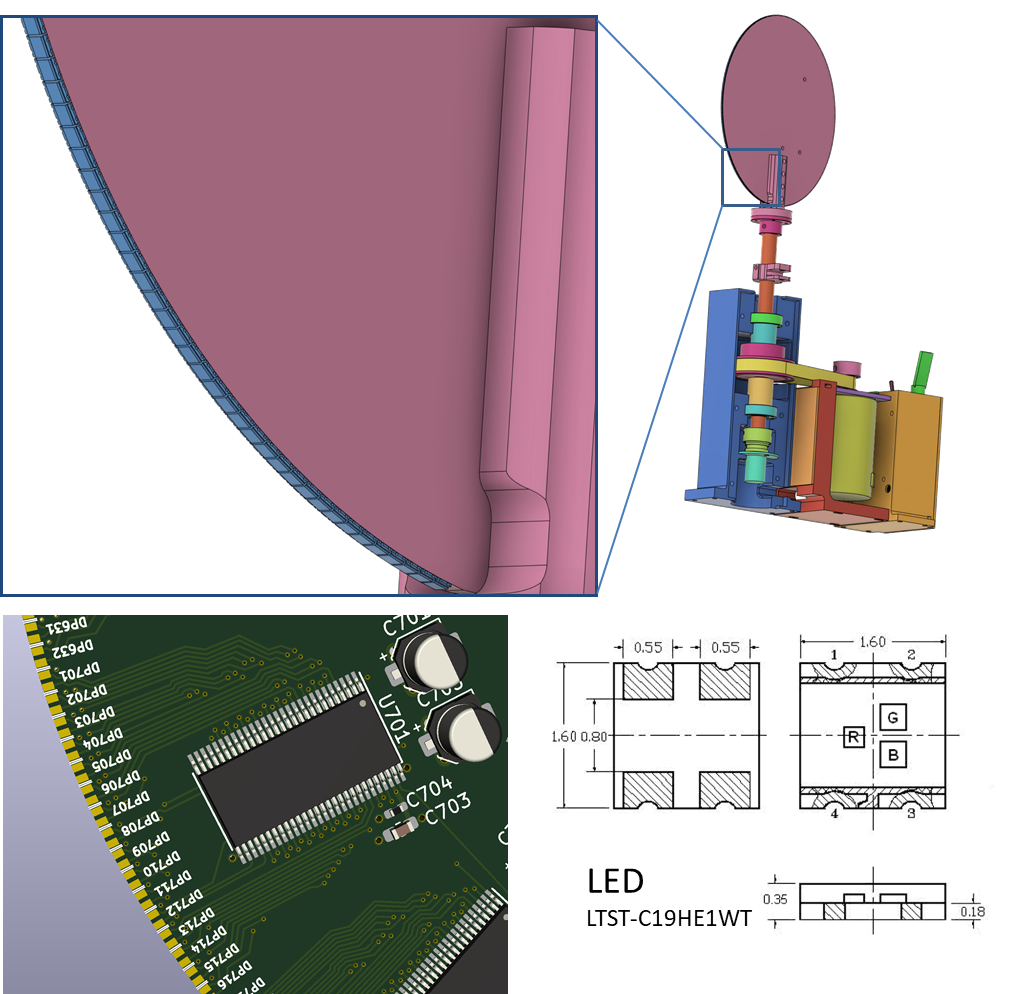
I was a little clever with the LEDs. If I had mounted them on the PCB as they are meant to be mounted, only that side of the board would be emitting light and I thought that would spoil the POV effect somewhat. So instead, I mounted the LEDs on the edge of the PCB - this was possible because I found a LED in a package that was exactly 1.6mm wide, the thickness of the PCB. By putting two of the LED pads on the top side of the PCB and the other two on the bottom side, I was able to mount the LEDs with solder bridges right to the edge of the PCB. This was a little tricky and took a little patience but didn’t take appreciably longer than regular soldering.
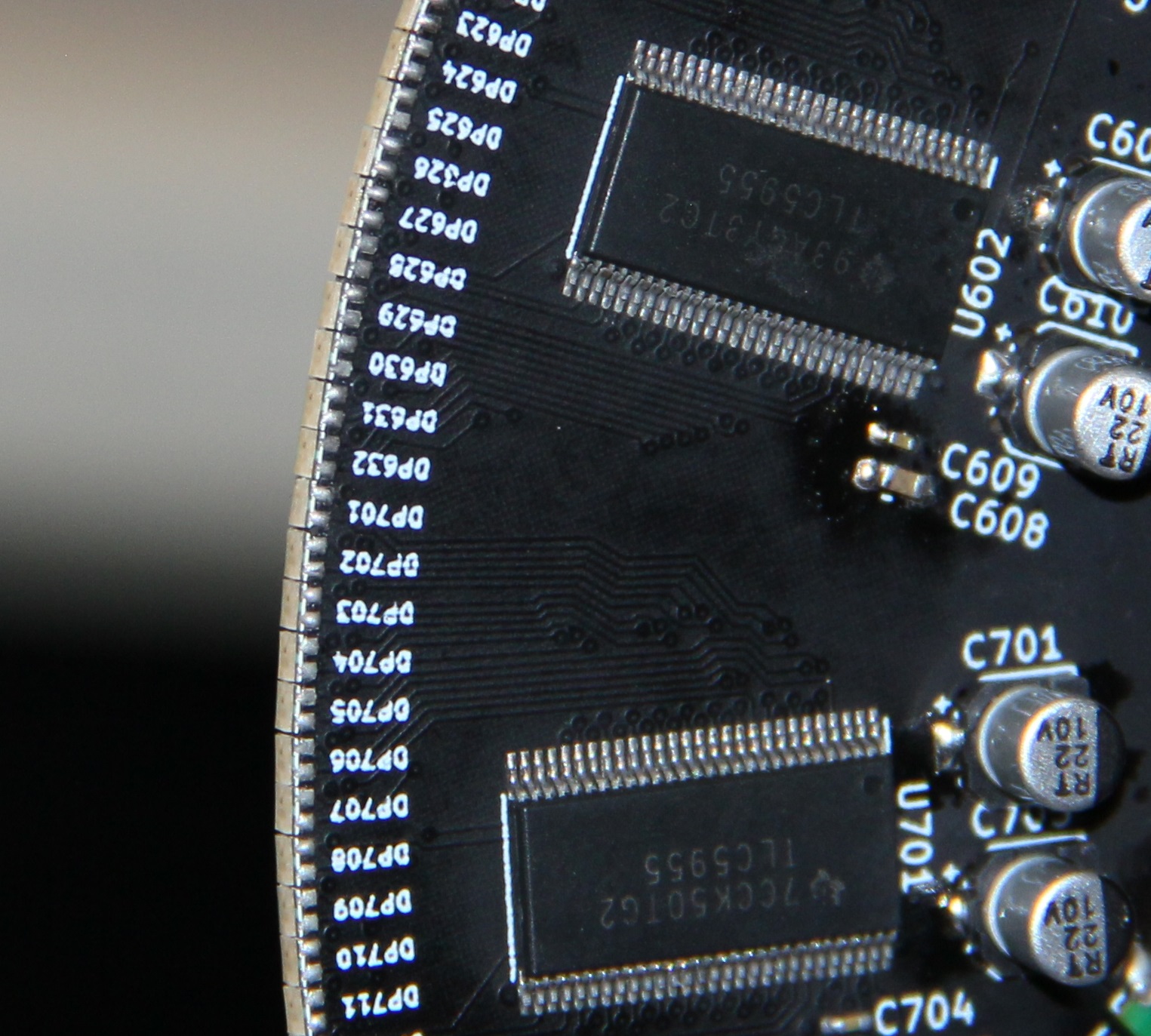
Unfortunately, some kind engineer at the PCB house thought they were doing me a favor and made the PCB a little bigger than I specified, thinking I couldn’t possibly want the pads to go right to the edge of the PCB. I was able to fix this by sanding the PCBs but the edge isn’t great - some of LEDs just never made great electrical contact, which you can see as dark stripes in the pictures and videos. In general, this worked well but again, I only planned to make one of these :)
 You’ll notice that the LEDs go pretty much all the way around the circumference of the board. I was a little too clever here. My intention was to create an interlaced image and increase the “Dots per Inch” by slightly offsetting the LEDs on the left side of the board with the ones on the right side of the board. The LEDs on the left side of the board would display the even lines of the image and the LEDs on the right side would display odd lines of the image but offset in time by half a revolution. Unfortunately, this didn’t work all that well. This was due to a few reasons:
- alignment is critical - the PCB must be aligned with the axis of rotation to better than 0.3 degrees. This is possible but a little fiddly. If the alignment isn’t good, the even/odd interlacing doesn’t work well, if at all.
- The LEDs aren’t point sources and they have no diffusion to make them more point like. Taking any odd/even pair, the green LED on the left side of the board lines up with the blue LED on the right side (assuming you get the alignment correct). If I were to do another rev of this board, I might try to rotate the LEDs on the right side so that the orientation of the LEDs is the same on both sides. I’d also think about some way to diffuse them.
Given a bit of time/patience, I could probably get this to work a little better than it is. Even without interlacing, having LEDs arranged like this essentially doubles the refresh rate, which means the board could spin slower. I never ended up populating all 256 LEDs and only use the 128 LEDs on the left side of the board to display images.
FPGA code
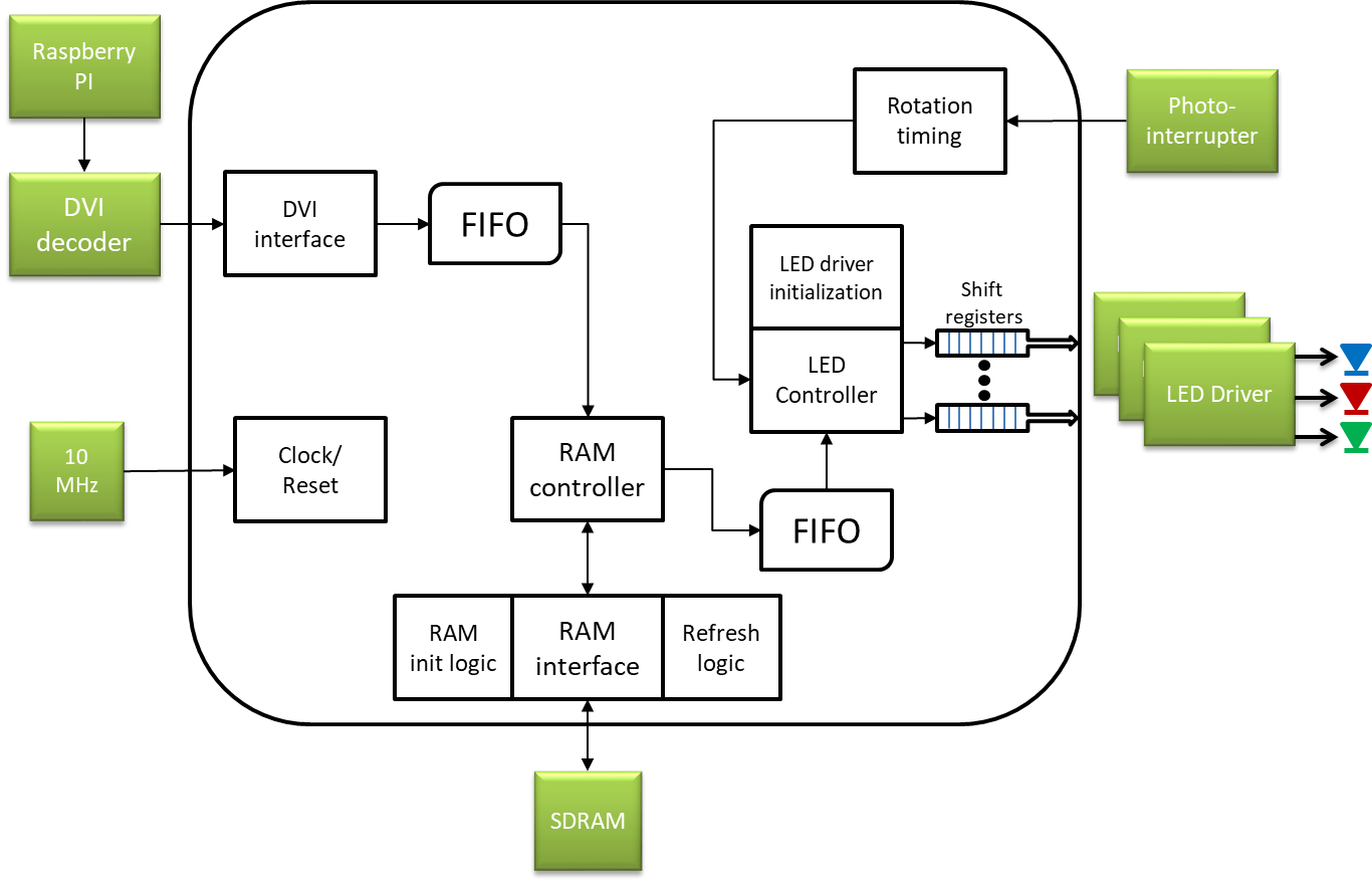
The FPGA handles taking the video stream from the Pi and storing individual frames in RAM, timing the rotation of the board and spitting out the bits to make the LEDs light up. The code is written in SystemVerilog. Some test benches and simulations were built to debug and verify the functionality of some of the parts but I can’t say that every part was tested that way. I took advantage of the Signal Tap Logic Analyzer to debug bits of the design in real-time, as well as using the Memory Editor - JTAG FTW! Because the board is spinning in normal operation, bits and bobs were put in the design to simulate the photo-interrupter signal when I wanted to use JTAG to probe the design. One thing not in the design at the moment is a concept of “front-wards” - however the board happens to be facing when it starts spinning ends up being the front (roughly). There’s a second input on the board for another hall-effect sensor or photo sensor that could be used to detect a zero position but I’m not too fussed about it.
Note that in the descriptions below, I’ll be ignoring any clock-domain crossing hardware - it’s there where needed.
Clock/reset
The reset module generates a short reset pulse that is used by all the modules. The clocks are generated by an external 10MHz oscillator that drives an internal PLL. Three clock frequencies are generated:
- SDRAM_clk : 90MHz - used to drive the SDRAM and most internal logic
- SCLK_X2 : 40MHz - used to drive the serial communications to the LED drivers
- GSCLK : 31.764706MHz - used to drive the LED drivers PWM circuits (kind of a weird frequency - I think this was just the closest I could get to the frequency I wanted)
RAM controller
The RAM controller does a few things:
- it takes care of initializing the SDRAM.
- it also takes care of the periodic refreshes the SDRAM needs
- it arbitrates access to the SDRAM.
There are two things (ignoring refresh) that want to use memory - the DVI controller to write data to RAM and the LED controller to read data from RAM. Both these modules use FIFOs to buffer data. The RAM controller runs a loop that:
- checks if there’s data to write from the DVI FIFO - if so, it writes a burst of 8 words
- checks if there’s a read request from the LED controller - if so, it reads a burst of 8 words to the LED FIFO
Both the DVI and LED controllers provide the memory addresses they’re looking to write to/read from next.
This isn’t perfect and there are definitely optimizations to be had. But it works perfectly well for this application - I can tell by looking at the buffer underrun and overflow signals for the FIFOs.
DVI controller
The Pi spits out an image that is 1280x1024 pixels at a frame rate of 60Hz. The effective resolution of the display is 128 pixels by 1024 angular slices at a frame rate of 15Hz. DVI controller is responsible for taking the central 128 pixels of each 1280 display line from the Pi and storing those in memory. It also only stores every fourth frame from the Pi to match the display frame rate - the other frames are simply discarded.
The pixel data from the DVI decoder is 24 bits wide - 8 bits for each of red, green, and blue channels. To reduce memory bandwidth, the DVI controller stores only the high order 5 bits for the red and blue channels and 6 bits for the green channel, making a 16 bit word which is conveniently the width of the SDRAM data bus.
 Note that the Pi must output an image in the right orientation. The Pi output resolution must be at least 128 x 1024 pixels - the FPGA will take care of cropping the image appropriately. The frame format stored in RAM is 128x1024x16.
Rotation timing
The TurnTimer module is responsible for figuring out the orientation of the PCB. It does this by timing the interval between edges (rising or falling) of the photo-interrupter. The module is expecting 8 equally spaced edges because there are four “vanes” - see the Sensor mount section above. It works as follows:
- wait for a change in the sensor input - set a counter to 0
- on each SDRAM_clk clock pulse, increment counter by 1
- when another change in the sensor input is detected, verify that the counter count is within expected bounds (this helps detect when the PCB is just starting to spin up and prevents the image from being displayed)
- Take the count and divide it by the image height (i.e 1024) and the number of sensor edges (i.e. 8). Note that these divides are actually done by a simple right shift. The resulting error due to this shift operation causes less than a pixel’s jitter. The result of this operation is the number of SDRAM_clk pulses per unit of angular resolution - let’s call this quantity
step. - Set up another counter to count SDRAM_clk pulses modulo
step. Every time this counter rolls over, the code increments arowcounter that keeps track of the angular position - this counter counts from 0 to 1023 (the image height). As well, whenever the row counter changes value, a pulse is generated. Both the pulse and the row counter values are used by the LED module to figure out what to display on the LEDs and when.
The quantity step does change significantly as the motor rotates - this indicates that the angular speed isn’t rock-steady. With a single “vane”, this jitter resulted in about 8-12 pixels of jitter in the image. Increasing the number of vanes has dropped the jitter to less than a pixel, resulting in a much nicer image.
LED Controller
After reset, the LED controller will send out bits to initialize each of the TLC5955s. This bitstream is hundreds of bits long and includes setting the operating mode of the chips as well as setting the individual LED and global brightness levels. I found I had to turn down the brightness of the LEDs to get usable contrast and also had to decrease the brightness of the green LEDs relative to the blue and red brightness to get a good color balance. Of course, because each serial line drives a pair of TLC5955s in series, the initialization bitstreams need to be sent twice.
Once the initialization is complete, the module waits for valid pulses and row counts from the TurnTimer module. Once a new row is detected, the module calculates the memory address for that row and requests a read operation from the RAM controller to fill the LED FIFO.
Once the LED FIFO is full, the LED controller waits until the next row is detected. It then converts the 16 bit color data that comes from RAM to the 24 bits the TLC5955s need. It does this by parsing the 16 bits into separate red (5 bits), green (6 bits), and blue (5 bits) values and then using a look up table for each color to generate an equivalent 8 bit value. These look-up tables also perform gamma correction. The values are shunted to a number of shift registers (one for each pair of TLC5955s) and then clocked out to the TLC5955s.
Conclusion
This was a really fun project and I’m happy with the result. There are definitely some changes I would make if I were to do this again but that’s probably not going to happen.
When I started this project, I also toyed with building it in a different form factor. In this other version, there would be a number of spinning “arms”, all spinning on the same axis but stacked on top of each other and offset from each other angularly. Each arm would contain either 16 or 32 LEDs, and there would be a total of 16 or 8 arms (respectively) stacked vertically. A PCB at the bottom would contain all the control electronics. This would be more of a volumetric display - might be fun to build at some point!